Pic06-19109 |

Description:
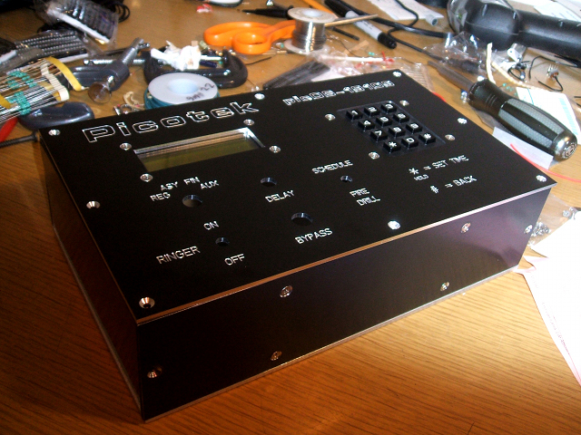
I wanted to make a keypad to LCD interface, so I decided to build a hardware version of a school bell module. Everything worked out great, but I did have some problems on the CMOS 74C922 encoder. It seems like it's very sensitive to noise so after I isolated the data output from the power cables it seemed to work fine.
Construction:
I got the front panel made by Front Panel Express. They're a great company making the final product look very profesional. And they included some gummy bears also when my panel was delivered. And yes, I did lose the bet with my friend Jake Kubena for my deadline, but it doesn't really matter since it works now and will be put to use. So now I have a fancy alarm clock that can switch up to 25 amps of current (but I haven't fully tested the output).
The hardest part was making an accurate time-base circuit that at most would lose or gain about a second every month or so. At the time I didn't know how to use timers and inturrupts and I wanted to stick with using the Basic Stamp 2. So after a lot of trial and error I came up with this CMOS timing circuit using a Pierce Gate ocsillator buffered by a 4049 Hex inverter divided by a 4040 and some 4017 ICs. I think it was a little overboard with hardware, but it's super-accurate. The scgematics and PCB design can bee seein in the attachments below.
Pic06_Schem_1.pdf
Pic06_Schem_2.pdf
One_Sec_Time_Base_Schem.pdf
Pico06/One_Sec_Time_Base_Layout.pdf
Pic06_PBASIC.txt
So I actually haven't fully tested the solid-state relay output so no guarantees on the design and/or function of that part. As soon as I get some time and workspace I'll put it all back together and at least have a fancy alarm clock since the school had already gone with a computer program for it's bell system.